Showing posts with label Drone. Show all posts

Tuesday, October 25, 2016

Request for Proposal - Hurricane Response UAS Design

Mission
The mission for the request for proposal that relates to hurricane damage and insurance claim collection via UAS. After large hurricanes, infrastructure often is limited, damaged to roads and pathways is limited due to fallen trees and power and communications networks are often limited if not completely destroyed.  In order to facilitate quick insurance claims, the ability to gather photographs immediately after the hurricane is vital. Not only with his data help insurance adjusters, but it could also augment a governmental response to the damage by helping predict and plan required resources and support. In order to create a system capable of accomplishing this mission, many parts of the system can come from Commercial Off the Shelf (COTS) products. The majority of the design effort will go into ruggedizing both the air vehicle as well as ground control station in addition to finding ways to power both the air vehicle and ground station without a reliable power source. The entire process from design and testing should take no longer than one year.
Derived Requirements
1.                  Transportability
1.1      Transportation case weight
1.1.1        Transportation case shall be authorized for checked baggage on airline.
1.1.2        Transportation case shall fit in sedan trunk
1.1.3        Transportation case shall be man portable (50LBS or less)
1.2   Transportation case as charger
1.2.1        Transportation case shall serve as charging station for air vehicle.
1.2.2        Transportation case shall serve as charging station for GCS.
1.3      Transportation case ruggedness
1.3.1        Transportation case shall be waterproof per IP68 rating.
1.3.2        Transportation case shall be drop proof from 5 feet.
1.3.3        Transportation case shall be dustproof per IP68 rating.
2.                  Data-link
2.1  Data-link frequency
      2.1.1 Data-link shall not interfere with emergency rescue communications.
      2.1.2 Data-link shall communicate without external network assistance (no LTE).
2.1.3 Data-link shall be resistant to interface from external influence.
2.1.4 Data-link shall be encrypted.
2.2   Data-link distance
      2.2.1 Data-link shall extend to at least 2 miles.
      2.2.2 Data-link shall be line of sight only.
3. Ground Support Equipment
3.1   Power Generation
      3.1.1 Power generation shall be from external generator (gasoline).
      3.1.2 Power generation shall be from 12VDC (car charger).
      3.1.3 Power generation shall be from solar panels.
      3.1.4 Power generation shall be adjustable between gen/vehicle/solar via simple switch.          
3.2   Image processing
      3.2.1 Image processing shall be done off site.
      3.2.2 Image processing shall be transmitted via cellular network
      3.2.3 Image processing shall be transmitted via satellite network
      3.2.4 Image processing shall be transmitted via WIFI
      3.2.5 Image processing shall automatically transmit via lowest cost network available. 
3.3  On-site maintenance
      3.3.1 On-site maintenance package shall support operations for one-week mission
      3.3.2 On-site maintenance package shall fit inside transportation case
      3.3.3 On-site maintenance package shall provide common spares for one-week mission
      3.3.4 On-site maintenance package shall include common tools for one-week mission

Testing Requirements:    
1.                  Transportability
1.2      Transportation case weight
1.2.1        Check complete transportation case with airline common carrier
1.2.2        Place complete transportation case in trunk of typical sedan 
1.2.3        Weight complete transportation case to determine if under 50 pounds.
1.2   Transportation case as charger
1.3.4        Conduct charging operations via transportation case for air vehicle 
1.3.5        Conduct charging operations via transportation case for GCS 
1.4      Transportation case ruggedness
1.4.1        Submerge transportation case in 1 meter of water for 30 minutes then inspect.
1.4.2        Drop transportation case from 5 feet then inspect for damage.
1.4.3        Expose transportation case to dust for 30 minutes then inspect.
2.                  Data-link
2.1  Data-link frequency
      2.1.1 Operate data-link within close proximity of fire department and police department.
      2.1.2 Operate data-link in a location that does not have LTE network.
2.1.3 Operate data-link in a location that is exposed to exposed high voltage powerlines.  
2.1.4 Attempt to intercept and exploit encrypted data-link
2.2   Data-link distance
      2.2.1 Operate data-link past 2 miles and check for signal loss.  
      2.2.2 Operate data-link beyond line of sight and check for signal loss.  

3.         Ground Support Equipment
3.1   Power Generation
      3.1.1 Power system via gasoline generator and attempt a full charge cycle.
      3.1.2 Power system via 12VDV car port and attempt a full charge cycle.
      3.1.3 Power system via solar panels and attempt a full charge cycle.
      3.1.4 Swap power source during charging cycle and check for proper switching.            
3.2   Image processing
      3.2.1 Send data to offsite location for processing.  
      3.2.2 Send data to offsite location for processing via cellular network.  
      3.2.3 Send data to offsite location for processing via satellite network
      3.2.4 Send data to offsite location for processing via WIFI
      3.2.5 While sending data check for proper network swap according to net availability    
3.3  On-site maintenance
      3.3.1 Operate the system for a week with no external maintenance support.
      3.3.2 Pack the maintenance package into transportation case and ensure compliance.  
      3.3.3 Operate the system for a week with no external maintenance part support
      3.3.4 Operate the system for a week with no external maintenance tool support
             
Development Process and Timeline
             The method of development for this system will required multiple teams to work with both uniquely new designs as well as modify COTS components. Due to the fact that most components will not need to be designed from scratch the process should be slightly quicker. The entire timeline of all 5 phases will be approximately 12 months from concept design to production. One of the key processes during all phases of development is the requirement for an overarching systems engineer to ensure system integration is occurring continuously. Ensuring the components are subject to phased testing and validation would assist in ensuring development was both on time and in compliance with requirements through the entire design process (Sadraey, 2010). In regards to the phases of development the will be broken down as follows:

Phase 1: Concept Design- Build conceptual solution to above requirements. (2 month)  
Phase 2: Preliminary Design- Determine what COTS components can be used and integrate and design new and unique components as per the requirements above. (2 months)
Phase 3: Detail Design-Teams design production ready systems that integrate both COTS and non-COTS components and integrate into total system design plan. (3 months)    
Phase 4: Test and Evaluation- Utilize the testing requirements above in order to ensure sub-system integration between teams is conducted to standard.  Selection of test sites and procedures will be accomplished.  (2 month)
Phase 5: Production- Selection of production site, marketing, and distribution will be considered. (3 months)

Testing Strategies: Due to the heavy reliance of both ground support equipment and power generation components, the testing strategies of this system will focus on the integration of all the major components of this system. In order to test the system properly, the key will be finding a location that is representative of a post hurricane disaster area. In order to provide a controlled environment as well as the attributes that are similar to a hurricane effected area, remote sites must be used. The capstone test and evaluation exercise should occur in a location with limited vehicle mobility, limited power resources, limited network connectivity, and for a duration of at least 7 days. The location will not be resupplied of any system parts, tools, or maintenance parts. This exercise will simulate the conditions that this system may meet when deployed to a disaster site, and the duration would simulate the typical time on the ground this system would remain without support from the rear.
Design Rational
            The major themes used to build the design requirements were durability and self-sufficiency. In regards to durability, the aircraft will need to be shipped, flown, driven, or carried in many different vehicles to reach areas effected by hurricanes. In order to protect the system, while at the same time allowing a single person to transport it, a high level of detail was put on the transportation case. In order to reduce weight and complexity, allowing the transportation case to act not only as a protective case, but also a charging stations and physical location of the GCS helped reduce cost and weight while decreasing additional equipment requirements. The transportation box’s resistance to the elements was vital due to the possibility of the system being stored outside if conditions do not allow for climate controlled indoor storage.
The aspect of self-sustainability is vital due to the fact that after a hurricane, the USPS, UPS, FedEx and other shipping options will often be limited due to destruction of infrastructure such as roads, runways, and ports (Cleary, 2016). The need to have all maintenance parts and tools stored in the transportation case will allow the sole operator of the system to deploy forward into the destruction zone without the need to trek back and forth, which would be both logistically difficult and time consuming. The ability of a single operator to gather multiple claims in a period of week while deployed forward will provide insurance companies with a marked advantage over there competition.
The power and network requirements presented also allow for near real time information flow from the destruction zone to a processing center regardless of power and network availability, which would most likely be either degraded or destroyed following a hurricane. The use of satellite networks, solar power or generators helps not only deploy to areas with limited infrastructure, but also allow for continuous operations without the need to return to the rear.
The entire system was designed to support long term self-contained operations in areas with degraded or destroyed infrastructure. The concept of sending out a small package with a single operator will reduce operational costs as well as logistical costs while maximizing the number of claims an insurance company to collect. The system will also decrease the reaction time that traditional insurance companies need to provide proper insurance claim coverage in hurricane affected areas. 
References
Cleary, T. (2016, October 06). What Is a Category 4 Hurricane? 5 Fast Facts You Need to Know. Retrieved October 25, 2016, from http://heavy.com/news/2016/10/what-is-category-4-hurricane-matthew-damage-strength-history-definition-wind-speed-storm-surge-facts-names/

Sadraey, M. (2010). A Systems Engineering Approach to Unmanned Aerial Vehicle ... Retrieved October 25, 2016, from http://enu.kz/repository/2010/AIAA-2010-9302.pdf 

Tuesday, October 18, 2016

UAS Missions and their Respective Attributes, Challenges, and Legalities

            There are many missions that unmanned aerospace systems (UASs) accomplish in both the public and civil realms. One of the most well suited missions to UAS is aerial Intelligence, Surveillance, and Reconnaissance (ISR). This mission set it not only a military mission, it is also conducted by police, border patrol, and FBI. All agencies that conduct aerial ISR via UAS share many of the same tactics techniques and procedures to accomplish the task. The type, size, and design of the UASs used in this mission vary widely based on where the mission is being conducted, the budget that a particular agency has for the mission, as well as other mission related constraints that are unique to each agency.     
            Three examples of platforms that accomplish the role of aerial ISR are the MQ-1C Gray Eagle which is used by the US Army, the MQ-8 Fire Scout which is used by the US Navy, and the Qube which was used by the Grand Forks, ND Police department to make its first night time arrest aided by a UAS (Koebler, 2014). The MQ-1C is a standard large fuel powered fixed wing UAS designed for launch and recovery via a 5,000ft runway. The Gray Eagle is capable of flying beyond line of sight as well as loitering for over 25 hours. This long loiter time and extended range provide the US Army with a powerful and capable system for aerial ISR (GA-ASI, 2016). 
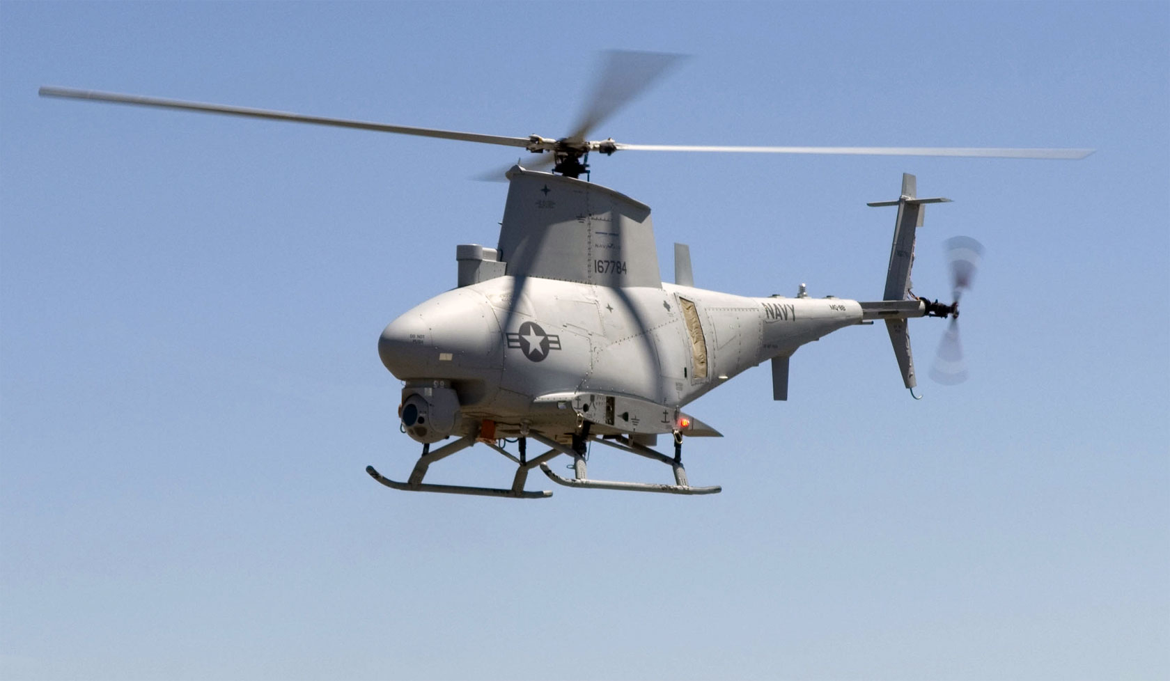
The MQ-8 Fire Scout is used by the US Navy to conduct aerial ISR, but it is a rotary wing platform which aids in launch and recovery from ships and boats. The system is capable of flight up to 16,000ft as well as can loiter for over 12 hours. While not as capable as the Gray Eagle, the Fire Scout has the huge advantage of vertical takeoff and landing, which is vital when operating at sea (Northrup Grumman Inc., 2016). 
The Qube by AeroVironoment is a small battery powered quadcopter UAS that is utilized by the Grand Forks, ND police department to aid in criminal surveillance, which is the police version of ISR. The Qube is capable of only 40 minutes of flight and has a line of sight range of only 1km, but meets both the mission requirements and budgetary constraints of a small police department (AeroVironment Inc., 2016).
            The mission requirements vary depending on where and when the mission takes place, but there are some major considerations that must be taken in to account when selecting a UAS platform. Most aerial ISR systems need to be able to gain a vantage point that humans cannot typical achieve on foot. This means that they need to be well above the target. For high value targets in Afghanistan it could mean 20,000ft loiter altitude. For a ship or marine target, 10,000ft above the ocean may be the right solution. For a police chase in an urban area, a 400ft altitude could be adequate. The other main mission task that must be executed is relaying the video photography of the target back to the operator in near real time. Regardless of size, platform type, or cost, this function is accomplished at all levels for aerial ISR UASs.
            The major challenges for conducting aerial ISR can be two fold, there are platform based challenges as well as payload based challenges. In terms of platform challenges, achieving beyond line of sight flight is expensive and technologically advanced. The use of third party satellites is expensive as well as complex. Another aspect of flying beyond line of sight domestically is that is regulatory restrictive (Anderson, 2016). One Major benefit of utilizing UASs for aerial ISR is that they can remain in the air longer than most other manned platforms. Compared to systems like the MQ-12 Liberty manned airplane that is flown by the US Air Force, most UASs regardless of size can outlast it while conducting an ISR mission. The MQ-12 can only stay aloft for 6 hours without having to break station to refuel (Airforcetechnology.com, 2016). The MQ-1C can last a full 25 hours on one tank of fuel (GA-ASI, 2016).
            There are multiple legal and moral issues that often are challenging for UAS to be utilized in aerial ISR mission, and even more so when UASs are equipped with munitions such as the hellfire missile. In the case of a military UAS conducting ISR and firing hellfires there is a moral issue as to who is to blame in case of collateral damage cause by improper target identification, or lack of target area situational awareness (McGuire, 2015). There are major legal issues when conducting ISR domestically by the police. The main issue is privacy. Privacy is a huge concern for the American public, and when conducting police action, the use of a UAS could require a warrant depending the state. California is a very conservative state when it comes to UAS use by the police. Recently the state assembly approved a law requiring police to get a warrant to use a UAS to conduct a search (Bailey, 2014). Other states are working through litigation to determine the legality of UAS surveillance by police, but there are many challenges both perceived and actual to utilizing UASs for aerial ISR both domestically and deployed.       
References
AeroVironment Inc. (2016). Visit AeroVironment Inc. Retrieved October 18, 2016, from https://www.avinc.com/uas/view/qube
Anderson, R. (2016, September 24). The opportunities and challenges of flying drones beyond line of sight (BLOS) | Commercial Drones Blog | Aviassist. Retrieved October 18, 2016, from http://www.aviassist.com.au/commercial-drones-blog/opportunities-challenges-flying-drones-beyond-line-sight-blos/
Bailey, R. (2014, August 05). California Assembly Passes Bill Requiring Police to Get a Warrant for Surveillance Drones. Retrieved October 18, 2016, from http://reason.com/blog/2014/08/05/california-assembly-passes-legislation-r
GA-ASI. (2016). Gray Eagle UAS. Retrieved October 18, 2016, from http://www.ga-asi.com/gray-eagle
Koebler, J. (2014, October 2). Police Used a Drone to Chase Down and Arrest Four DUI Suspects in a Cornfield. Retrieved October 18, 2016, from http://motherboard.vice.com/read/police-used-a-drone-to-chase-down-and-arrest-four-dui-suspects-in-a-cornfield
Maguire, L. (2015, September 26). The Ethics of Drone Warfare. Retrieved October 18, 2016, from http://www.philosophytalk.org/community/blog/laura-maguire/2015/09/ethics-drone-warfare
Northrup Grumman Inc. (2016). Fire Scout. Retrieved October 18, 2016, from http://www.northropgrumman.com/Capabilities/FireScout/Pages/default.aspx?utm_source=PrintAd


Tuesday, October 4, 2016

Unmanned Aerial Systems in National Airspace

     Unmanned aircraft are a vital asset in today’s world. They have made aerial photography and videography cheaper and more accessible to both hobbyists and small business owners.
Today, the major hurtle is UAS integration into national airspace (NAS). One of the major aspects to integration of UAS into NAS is the ability for systems to sense and avoid other aircraft or obstacles. In the current FAA regulations, the term “see and avoid” exist, but in the future “sense and avoid” will be applied (Carey, 2013). Until that point UASs are unable to comply with the requirements, but this has not stopped companies and the military from working towards smart solutions to the providing a sense and avoid system that are dependable enough to garner FAA approval and support.

     The techniques for monitoring separation from both manned and unmanned systems come in multiple forms. The overarching concept, regardless of technique, is that the UAS is informed of nearby traffic and can execute a predictable solution that will provide regulatory separation. The two major techniques to gathering this traffic information can be categorized as ground based or airborne based sensing. Ground based sensing utilize radar systems similar to air traffic control agencies. The major difference is that these radar systems integrate directly into the ground control station (GCS) of the UAS (SRC Inc. 2016). The airborne technique relies on advanced sensors being equipped directly on the air vehicle portion of the UAS. A lot of research is going into the development of micro radar systems that would be able to fit a highly capable radar system into a very small package (Gorwara, 2014).
 
     Some of the major considerations that need to be factored in when deciding between ground based sensing or airborne sensing needs to be attributed to both the size and type of UAS airframe in questions. Small UASs need to be very cognizant of size power and weight of any additional sensors that need to be added to the air vehicle. These systems may benefit from a ground based system that is able to communicate with the ground control station. Additionally, micro radar systems are being produced to provide small quadcopter sized UASs with a robust ability to sense and avoid traffic with light weight and low power solutions (Gorwara, 2014).  Large UASs like military grade UASs have a large payload capacity and a large power source capable of both carrying and powering complex sensors that can provide adequate sense and avoid capabilities. Another aspect to consider is the type of airframe in question. A small quadcopter may move slowly and within a relatively small range. This means less powerful sensors could be used to provide the separation and spacing required. Large fast fixed wing system could fly at high altitudes and at high speeds with an enormous range, so providing powerful onboard solutions may make the most sense.

     Some larger systems like the MQ-4 global hawk actually have terminal collision and avoidance system (TCAS) which is used on most large commercial manned aircraft. There is also research into a new system call Airborne Collision Avoidance System for Unmanned Aircraft or ACAS Xu for short. This system will integrate with TCAS as well as provide autonomous functions that will support proper sense and avoid decision making if the UAS has lost link or is in autonomous flight (NASA, 2015).
 
     Another current initiative is the use of a system called the ground based sense and avoid system (GBSAA) by SRC Inc. This system is currently being installed by the US Army at posts that are hubs for large UAS training. Fort Hood and Fort Campbell are both test beds for this technology (Mishory, 2016). The system utilizes powerful and expensive ground based radar dishes to directly communicate any traffic advisories directly to the GCS of the UASs operating within its area of responsibility. This system can detect both manned and unmanned aircraft as well as other airborne obstacles. The benefits of this system are that just one GBSAA can provide coverage for multiple aircraft working in a defined area. Also, GBSAA does not add any additional power or weight requirements to the actual air vehicles that are utilizing its information (SRC Inc., 2016).

     Regardless to size and type, the need for FAA approved sense and avoid systems is vital to the integration of UAS into NAS. By understanding the limitations and capabilities associated with the size and type of a UAS will help engineers provide the best solution to each system on a case by case basis. The need to ensure the right capability is equipped on the right system is also vital in reducing excess costs and ensuring the general UAS user base is capable and willing to equip their UASs with these systems when it becomes available.  Additionally, integrating the UAS sense and avoid technology into manned sense and avoid systems like TCAS will be vital to future integration.      

 References
Carey, B. (2013, June 22). FAA Plans Unmanned 'Sense and Avoid' Rule in 2016. Retrieved
October 03, 2016, from http://www.ainonline.com/aviation-news/air-transport/2013-07-22/faa-plans-unmanned-sense-and-avoid-rule-2016

Gorwara, A. (2014). Doppler micro sense and avoid radar. Retrieved October 3, 2016, from http://pmi-rf.com/documents/DopplerMicroSenseandAvoidRadarPaper.pdf

Mishory, J. (2016, June 16). Initial UAS flights using GBSAA system at Ft. Hood have been delayed. Retrieved October 03, 2016, from https://insidedefense.com/daily-news/initial-uas-flights-using-gbsaa-system-ft-hood-have-been-delayed

NASA. (2015, January 25). NASA, FAA, Industry Conduct Initial Sense-and-Avoid Test. Retrieved October 03, 2016, from http://www.nasa.gov/centers/armstrong/Features/acas_xu_paves_the_way.html

SRC Inc. (2016). Ground-Based Sense and Avoid Radar System. Retrieved October 03, 2016, from http://www.srcinc.com/what-we-do/radar-and-sensors/gbsaa-radar-system.html

Tuesday, September 13, 2016

The TDR-1 (1943) vs The MQ-1C (2016)

     One of the oldest UASs that utilizes a video camera and had the ability to drop ordinance is the TDR-1. In 1943 the US Navy worked with both the RCA television company and the Interstate Engineer Company to produce the TDR-1. This aircraft was made out of plywood and tubular steel and weight in at over 5,900 pounds (not including munitions). The aircraft was capable of flying over 495 NM in a single mission and could carry a 2000 pound bomb or torpedo. The radio control system and RCA television camera could be broadcasted about 8 miles to either a ground control station or a flying mothership. Considering TVs and radio controlled systems were just being invented around this time, it was an extremely cutting edge system that proved to be a capable system in combat. In 1945 the TDR-1 actually saw real combat and took out an enemy ship off the cost of the Russel Islands (Newport News Ship Building Inc., n.d.). Looking at UASs of today this system can be compared to the MQ-1C Gray Eagle due to their similarities and methodologies.

The TDR-1 Assault Drone


Similarities
            The TDR-1 and the MQ-1C both utilize video capture as a form of munition guidance and target acquisition. Both systems utilize a ground control station and portions of the electromagnetic spectrum to control both the aircraft itself and the munitions they carry. Both were fixed wing platforms and both had quite a good mission endurance range. The TDR-1 could carry over 2000 pounds of either bomb or torpedo and the MQ-1C can carry 400 pounds of precision guided munitions (GA-ASI Inc., 2016). These major broad stroke concepts are near mirror images, but upon further investigation one can see that much of the technology equipped on the MQ-1C has truly evolved dramatically since 1943. Many of the sub systems that have evolved did not only evolved for the UAS industry, but can attribute their evolution to the computer evolution, the camera evolution, and aeronautical evolution that has taken place since 1943.

The MQ-1C Gray Eagle 


Differences
            Some of the major differences has to do with the fact that integrated circuits did not exist until 1958 (TI Inc., 2008). Much of the computing was accomplished by vacuum tubes. This limited command and control to very simple techniques. Setting the altitude for the TDR-1 was done through dialing a rotary phone dial and have each number represent a particular altitude above ground level (Newport News Ship Building Inc., n.d.). As global navigation techniques evolved into GPS and INS sensors, the idea of following a UAS with a mothership or using just line of sight to figure out where it is became obsolete. The MQ-1C is equipped with redundant GPSs and INSs in order to ensure the operator knows exactly where the system is even when operating via satellites beyond line of sight (GA-ASI., 2016). Another major difference between the TDR-1 and the MQ-1C is that the MQ-1C utilizes digital communication technology. Along with an advancements in camera technology, the swap to digital communication methods allowed for much higher bandwidth communication as well as much further communication distances to include beyond line of sight.

The Future
            Looking even further into the future and taking notes from what we have seen evolved since 1943, one can see there is a bright future of UAS technology. Some of the major initiatives in the department of defense have to deal with simplification and automation of unmanned systems in general. Taking the need for highly skilled operators, and huge logistic supply chains out of the equation is one of the most vital aspects of future success of many of the current UAS programs. Much of these goals will be accomplished through standardizing future technologies, creating modular payload and interoperability with both manned and other unmanned systems (Department of Defense, 2013).   

References:

Department of Defense. (2013). Unmanned Systems Integrated Road Map FY 2013-FY2038. Retrieved September 13, 2016, from http://www.defense.gov/Portals/1/Documents/pubs/DOD-USRM-2013.pdf

GA-ASI Inc. (2016). Gray Eagle UAS. Retrieved September 13, 2016, from http://www.ga-asi.com/gray-eagle

Newport News Ship Building Inc. (n.d.). TDR-1: First Operational US Navy Drone... Successful in Combat in 1944! Retrieved September 12, 2016, from http://www.nnapprentice.com/alumni/letter/TDR_1.pdf   

TI Inc. (2008). Texas Instruments - 1958 Jack Kilby invents integrated circuit. Retrieved September 13, 2016, from http://www.ti.com/corp/docs/company/history/timeline/semicon/1950/docs/58ic_kilby.htm
    

US Army. (2016). MQ-1C Gray Eagle Unmanned Aircraft System (UAS). Retrieved September 13, 2016, from http://asc.army.mil/web/portfolio-item/aviation_gray-eagle-uas/