Unmanned aircraft are a vital asset in today’s world. They have made aerial photography and videography cheaper and more accessible to both hobbyists and small business owners.
Today, the major hurtle is UAS integration into national airspace (NAS). One of the major aspects to integration of UAS into NAS is the ability for systems to sense and avoid other aircraft or obstacles. In the current FAA regulations, the term “see and avoid” exist, but in the future “sense and avoid” will be applied (Carey, 2013). Until that point UASs are unable to comply with the requirements, but this has not stopped companies and the military from working towards smart solutions to the providing a sense and avoid system that are dependable enough to garner FAA approval and support.
The techniques for monitoring separation from both manned and unmanned systems come in multiple forms. The overarching concept, regardless of technique, is that the UAS is informed of nearby traffic and can execute a predictable solution that will provide regulatory separation. The two major techniques to gathering this traffic information can be categorized as ground based or airborne based sensing. Ground based sensing utilize radar systems similar to air traffic control agencies. The major difference is that these radar systems integrate directly into the ground control station (GCS) of the UAS (SRC Inc. 2016). The airborne technique relies on advanced sensors being equipped directly on the air vehicle portion of the UAS. A lot of research is going into the development of micro radar systems that would be able to fit a highly capable radar system into a very small package (Gorwara, 2014).
Some of the major considerations that need to be factored in when deciding between ground based sensing or airborne sensing needs to be attributed to both the size and type of UAS airframe in questions. Small UASs need to be very cognizant of size power and weight of any additional sensors that need to be added to the air vehicle. These systems may benefit from a ground based system that is able to communicate with the ground control station. Additionally, micro radar systems are being produced to provide small quadcopter sized UASs with a robust ability to sense and avoid traffic with light weight and low power solutions (Gorwara, 2014). Large UASs like military grade UASs have a large payload capacity and a large power source capable of both carrying and powering complex sensors that can provide adequate sense and avoid capabilities. Another aspect to consider is the type of airframe in question. A small quadcopter may move slowly and within a relatively small range. This means less powerful sensors could be used to provide the separation and spacing required. Large fast fixed wing system could fly at high altitudes and at high speeds with an enormous range, so providing powerful onboard solutions may make the most sense.
Some larger systems like the MQ-4 global hawk actually have terminal collision and avoidance system (TCAS) which is used on most large commercial manned aircraft. There is also research into a new system call Airborne Collision Avoidance System for Unmanned Aircraft or ACAS Xu for short. This system will integrate with TCAS as well as provide autonomous functions that will support proper sense and avoid decision making if the UAS has lost link or is in autonomous flight (NASA, 2015).
Another current initiative is the use of a system called the ground based sense and avoid system (GBSAA) by SRC Inc. This system is currently being installed by the US Army at posts that are hubs for large UAS training. Fort Hood and Fort Campbell are both test beds for this technology (Mishory, 2016). The system utilizes powerful and expensive ground based radar dishes to directly communicate any traffic advisories directly to the GCS of the UASs operating within its area of responsibility. This system can detect both manned and unmanned aircraft as well as other airborne obstacles. The benefits of this system are that just one GBSAA can provide coverage for multiple aircraft working in a defined area. Also, GBSAA does not add any additional power or weight requirements to the actual air vehicles that are utilizing its information (SRC Inc., 2016).
Regardless to size and type, the need for FAA approved sense and avoid systems is vital to the integration of UAS into NAS. By understanding the limitations and capabilities associated with the size and type of a UAS will help engineers provide the best solution to each system on a case by case basis. The need to ensure the right capability is equipped on the right system is also vital in reducing excess costs and ensuring the general UAS user base is capable and willing to equip their UASs with these systems when it becomes available. Additionally, integrating the UAS sense and avoid technology into manned sense and avoid systems like TCAS will be vital to future integration.
References
Carey, B. (2013, June 22). FAA Plans Unmanned 'Sense and Avoid' Rule in 2016. Retrieved
October 03, 2016, from http://www.ainonline.com/aviation-news/air-transport/2013-07-22/faa-plans-unmanned-sense-and-avoid-rule-2016
Gorwara, A. (2014). Doppler micro sense and avoid radar. Retrieved October 3, 2016, from http://pmi-rf.com/documents/DopplerMicroSenseandAvoidRadarPaper.pdf
Mishory, J. (2016, June 16). Initial UAS flights using GBSAA system at Ft. Hood have been delayed. Retrieved October 03, 2016, from https://insidedefense.com/daily-news/initial-uas-flights-using-gbsaa-system-ft-hood-have-been-delayed
NASA. (2015, January 25). NASA, FAA, Industry Conduct Initial Sense-and-Avoid Test. Retrieved October 03, 2016, from http://www.nasa.gov/centers/armstrong/Features/acas_xu_paves_the_way.html
SRC Inc. (2016). Ground-Based Sense and Avoid Radar System. Retrieved October 03, 2016, from http://www.srcinc.com/what-we-do/radar-and-sensors/gbsaa-radar-system.html
Showing posts with label Sensors. Show all posts
Showing posts with label Sensors. Show all posts
Tuesday, October 4, 2016

Sunday, February 8, 2015
Data Format, Protocols, and Storage Methods of Mars Curiosity Rover
Data transfer between unmanned systems and ground control
stations is a challenge for any unmanned system. Data transfer between an
unmanned system and a ground control station which are planets apart becomes
even more of challenge given the limitations of our current technology.
Understanding the methods behind the Mars Curiosity Rover communications system
will help us gain understanding about data management, treatment, and movement
in any unmanned system. Additionally, being able to understand the onboard
sensor and how they interact with the data transfer architecture in terms of
power requirements, data storage requirements, and data treatment methods, will
help us analyze the current state of technology. Upon a detailed study of the current
situation, proposed future changes could streamline the entire data transfer
process from the sensor to the final product.
Data Format, Protocol, and Storage
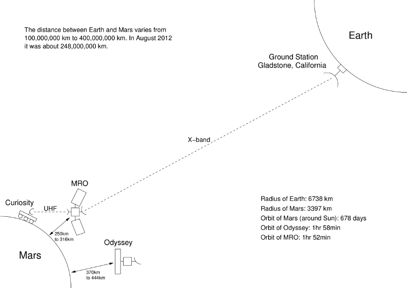
The Curiosity Rover has a network of satellites that
allows the rover on the surface of Mars to communicate with the ground control
station (GCS) on earth at high data rates. Unlike smaller unmanned systems,
direct communication between the ground station and the vehicle are
impracticable due to the power requirements and bandwidth limitations that
exits when transmitting data between Earth and Mars. The rover and the GCS can
be as far as 400,000,000 km apart, and to transmit data over that distance
while using a relatively feasible mount of power, the bandwidth peaks at 800 b/
s using the onboard high gain antenna, which utilizes X band frequencies (Gordon,
2012). This type of communication can transfer telemetry and navigational commands
to the rover, but sending raw imagery or data from one of its many sensors
would be extremely impractical. For large data the Curiosity Rover utilizes the
Mars Reconnaissance Orbiter (MRO) to relay its data back to earth. The MRO
orbits only 275km over the surface of Mars, which exponentially decreases the
power requirement to transmit large data files off the surface of Mars (Taylor,
2006). The orbiter is designed not only to relay and amplify signals back to Earth,
but it is an instrument of science loaded with its own sensors that are used in
conjunction with the rover. The final piece of the communications architecture
is the GCS. There are three large ground stations, one in Goldstone,
California, one in Madrid, Spain, and one in Canberra, Australia. These GCSs
are on a much larger scale than any terrestrial based unmanned system GCS. They
come standard with one 70m parabolic antenna and at least two 34m parabolic
antennas. By creating huge power hungry antennas on the earth, the size and
power required by the orbiter and rover to transmit and receive data can be
decreased (Gordon, 2012).
Onboard Sensors
In terms of sensors onboard Curiosity, there are many high
tech sensors that have a range of purposes (NASA, 2015). In an effort to study
data transfer techniques; analyzing the sensors with the highest data transfer
requirement will assist in understanding how to streamline the process in the
future. Some of the highest data producing sensors on the rover are the mast cameras.
There are two 2-megapixl cameras that not only capture imagery, but can be used
as a stereo pair in order to conduct 3D mapping of the rovers immediate
surrounds. Anyone with a background in photography would think 2MP cameras are
not the best choice for a 2.5 billion dollar space probe, but this is the first
step of the data treatment method utilized by the engineers on the rover
project. By utilizing a lower megapixel camera, the data transfer requirement
is decreased before utilizing compression, or other forms of data treatment.
The mast cameras utilizes a 1600 x 1200 pixel resolution interline camera
sensor (Cangeloso, 2012). This camera is capable of storing up to 5500 full
size images on the actual cameras memory itself, which acts as a buffer. This capture
resolution roughly translates to about a 1.4mb image file in its raw form
(Gordon, 2012). This is where the use of the MRO and UFH radio communication
come in. The UHF radio on the rover can pump out much higher bandwidth, which
is up to 256 kb/s. This is done with a 12 watts transceiver. If the rover was
required to send via its high gain antenna straight back to Earth via X-band
communications, data transfer could only top out around 800 b/s and required 15
watts of power. This would mean the same images would take much longer to
transmit and require the 15watt transceiver to be active and drawing energy for
a much longer period of time (Taylor, 2006). The power and time constraints
placed on the entire system when the MRO is not used would severely limit the
mission success of the rover.

Alternative Data Treatment Strategy
Since 2004, which is when Curiosity and the MRO were
designed many things have changed in terms of image compression and data
storage. Starting with the sensor, I would recommend the use of a higher
resolution camera pair, but include the use of lossy image compression. This
would have two aspects, it would increase the native resolution and quality of
the imagery coming from the mast camera set, but the lossy compression would
reduce the data back into a manageable data set that would be easily relayed
back to earth (Chin, 2013). The second methodology in terms of data transfer
would be increasing the onboard storage capacity from about 8 GB to 100 GB per
sensor. Along with the increased storage, I would implement a server based
tagging method to the imagery that would add metadata and allow scientist to
query the server and then pull full resolution imagery as needed. Not having to
send back all the imagery at full resolution would save bandwidth to allow
simultaneous transfer of the “current view” low resolution imagery as well a
full resolution stills that are being queried by scientists for further
investigation.

Both data storage and processing power are increasing
exponentially every day. The physics of data transfer and the power required to
accomplish it are not as rapidly advancing as fast, and this is why
alternatives and advances in data transfer should focus on the digit aspects
rather than the electromagnetic aspects. Long distance laser data transfer may
be a long term solution to the current slower moving portions of the
electromagnetic spectrum that we utilize, but with todays rapid increase in
processing power, the near term solution may be in compression and processing
advances in data transfer.
References
Gordon, S. (2012, January 1).
Talking to Martians: Communications with Mars Curiosity Rover. Retrieved
February 8, 2015, from https://sandilands.info/sgordon/communications-with-mars-curiosity
Taylor, J. (2006). Mars
Reconnaissance Orbiter Telecommunications. DESCANSO Design and Performance
Summary Series, (Article 12). Retrieved February 8, 2015, from http://descanso.jpl.nasa.gov/DPSummary/MRO_092106.pdf
Makovsky, A. (2009). Mars Science
Laboratory Telecommunications System Design. DESCANSO Design and Performance
Summary Series, (Article 14). Retrieved February 8, 2015, from
http://descanso.jpl.nasa.gov/DPSummary/Descanso14_MSL_Telecom.pdf
NASA. (n.d.). Mars Science
Laboratory; Curiosity Rover. Retrieved February 8, 2015, from http://mars.nasa.gov/msl/
Cangeloso, S. (2012, August 9). Why
does the $2.5 billion Curiosity use a 2-megapixel camera? | ExtremeTech.
Retrieved February 8, 2015, from http://www.extremetech.com/extreme/134239-why-does-the-2-5-billion-curiosity-use-a-2-megapixel-camera
Chin, M. (2013, December 18). New
data compression method reduces big-data bottleneck; outperforms, enhances
JPEG. Retrieved February 8, 2015, from
http://newsroom.ucla.edu/releases/ucla-research-team-invents-new-249693
Wednesday, January 21, 2015
Bluefin-21’s Sensors and Advances in Maritime Sensors
By Brett Chereskin
Abstract
This paper provides an explanation
of the sensors and capabilities of the Bluefin-21 autonomous underwater vehicle
(AUV). There are four topics address within this paper. The first is an
analysis of marine sensors that support underwater search and rescue. The
second topic proposes modification to the AUV that would increase search and
rescue capability. The third topic proposes possible sea to air unmanned system
coordination, and the final topic weighs the pros and cons between manned and
unmanned systems in maritime sensor technology.
Introduction
The Bluefin-21 is an autonomous underwater vehicle (AUV) that is
build by Bluefin Robotix. This advanced maritime AUV has recently been used in
the search for Malaysia Airline flight MH370 and contains many sensors that are
perfectly suited to the underwater search and rescue mission (Chand, 2014). Understanding
the available sensors used on the Bluefin-21 will help determine if any
modification can be made that will increase it’s capabilities as well as if
integrating with unmanned aerial systems (UASs) could provide an increase to
its mission success. Additionally, by analyzing the advantages of sensors
suited to unmanned systems a clear understanding of this topic will be
gained.
The Sensors of Bluefin-21
The Bluefin-21 can be fitted with multiple
sensors depending on the mission requirement. One of the most commonly used
sensors for maritime search and rescue on the Bluefin-21 is the EdgeTech 2200-M
120/410 kHz side scan sonar (Chand, 2014). The EdgeTech 2200-M gathers side
scan and/or sub-bottom data using EdgeTech’s proprietary technology in water
depths up to 6000 meters (EdgeTech, 2015).
This proprioceptive sensor is specifically deigned for use in the
maritime environment due to the fact that only in water will acoustic/ FM sonar
sensors provide the best wave propagation and resolution. To note, one of the greatest advantages of
this particular sonar imagining sensor is that is uses full spectrum signal
processing that sends out a broad band transmitting pulse. One benefit of a
full spectrum system is the relative power savings over a conventional
continues wave sonar system. In order to obtain the same resolution, conventional
sonar would required 100 times more power compared to the full spectrum sonar
system (EdgeTech, 2015).
Possible Modifications
Upon analysis of the EdgeTech 2200-m on the
Bluefin-21, other than attempting to decrease weight and power consumption,
which are key to any unmanned system, I propose that the ability to network
multiple sensors via underwater acoustic networks should be integrated. Due to
the temporal constraints of any search and rescue mission, being able to cover
larger amounts of area in less time is essential. The Bluefin-21 uses an INS to
accurately track its positions, but allowing the position data to georeference
the EdgTech’s imagery would be the first step in the multi-sensor integration
(Bluefin-21, 2015). After georeferenceing, multiple sensors would need to
communicate the data in order to run algorithms that would optimize participating
AUV tracks so the multi-sensor system could map the largest possible area the least
amount of time.
Aerial Integration
In
order to network multiple sensors via underwater acoustic networks,
consideration must be made to the limitations of acoustic communication networks. Underwater acoustic communications are
generally recognized as one of the most difficult communication media in use
today (Stojanovic, 2009). Due to this limitation, an alternative could be the
introduction of an aerial command and control node, specifically an unmanned
aerial system capable of extended transit and loiter times as well as beyond
line of site communication of high bandwidth datasets. The multiple
Bluefin-21’s could surface at regularly scheduled intervals and upload key data
to the command and control UAS. The UAS would not only send the AUVs datasets
to the mission command center at real near time, but it could also provide
mission parameter changes to all other AUVs participating in a particular
mission set.
Unmanned vs Manned
In
terms of maritime sensors, there are a few key reasons why the use of AUVs over
manned systems is beneficial. One major reason has to do with sensor depth. In
terms of maritime sensor operation, it is known that attenuation of sonar
pulses and noise are a limiting factor in obtaining high-resolution products (Stojanovic,
2009). If sensors were limited to shallow depths due being mounted on manned
systems, the resolution during deep-water search and rescue would be limited.
If the system is mounted on an AUV like the Bluefin-21, which is capable of
diving to 4500 meters, it would be able to retrieve higher resolution products,
and possible dive deep enough to obtain true camera imagery of the bottom of
the ocean (Bluefin, 2014).
Conclusion
The
integration of unmanned systems into maritime search and rescue has taken
previously existing sensor technology to the next level. The ability to take
these sensors deeper and coordinate and optimize multi-sensor operations will
save lives in the near future. By further integrating the unmanned aerial layer
into the maritime layer, it will speed up data transfer and facilitate ad hoc
mission changes.
References
Chand , N. (2014). Unmanned/Autonomous Underwater Vehicles. SP’s
Naval Forces, Jun 2014 Issue. Retrieved from http://www.spsnavalforces.com/story.asp?mid=37&id=6
EdgeTech Corp. (2015). 2200-M
Modular Sonar System. Retrieved from
BlueFin Robotix Corp. (2015). Bluefin-21
Summary. Retrieved from http://www.bluefinrobotics.com/products/bluefin-21/
Stojanovic, M., & Preisig, J. (2009). Underwater
Acoustic Communication Channels Propagation Models and Statistical
Characterization. IEEE Communications Magazine Retrieved from http://web.mit.edu/millitsa/www/resources/pdfs/chmj-print.pdf
Subscribe to:
Posts (Atom)